
1. DRAM Volatility & Core Risks of Abrupt Power Outages
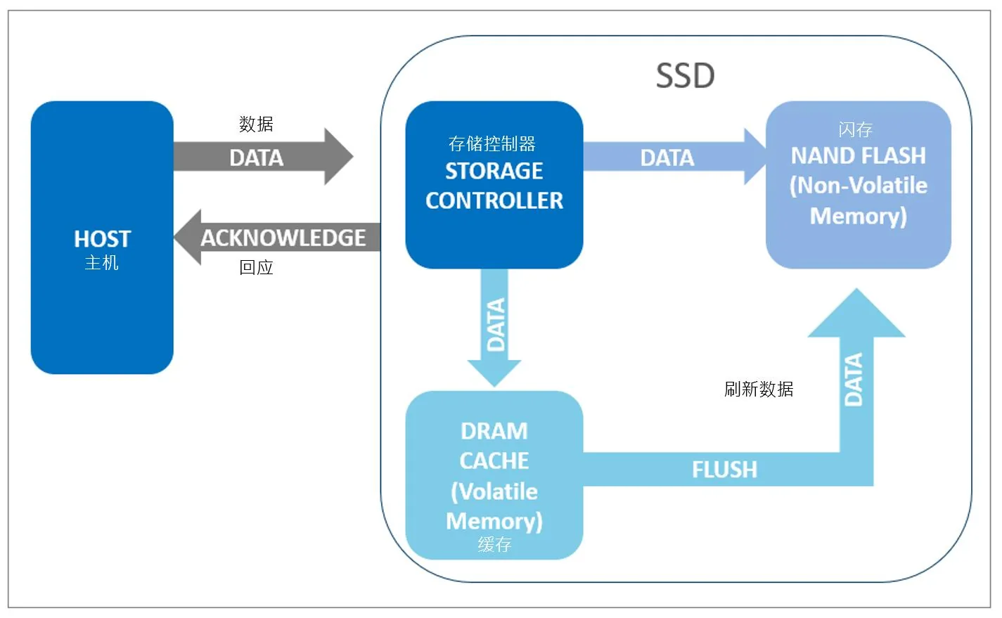
To achieve million-class IOPS and sub-millisecond latencies, modern enterprise SSDs utilize high-speed DRAM as write buffers:
- Data Flow Pipeline: The host issues write commands; the controller buffers hot data in volatile DRAM and returns an acknowledge to the host before asynchronously flushing to NAND flash.
- Vulnerability Window: DRAM is volatile memory. If external input power collapses, unflushed hot data buffered in DRAM vanishes instantly.
2. SSD Hardware Architecture & FTL Table Corruption Mechanism
The most catastrophic outcome of sudden power loss is not merely losing partial files, but the destruction of the Flash Translation Layer (FTL) mapping table:
- Logical-to-Physical Indexing: The FTL maps host logical block addresses (LBAs) to physical NAND blocks. For ultra-fast indexing, the primary FTL table resides actively inside DRAM cache.
- Mapping Table Crash Equals Drive Bricking: If power cuts interrupt an FTL flush or corrupt parity, the drive cannot identify partitions or controller firmware upon subsequent boot, manifesting as total drive failure (device drop).
3. pFail Protection Timing: Millisecond Five-Step Closed Loop
Hardware PLP is an active, synchronized system pairing dedicated hardware energy storage with high-priority firmware interrupts:
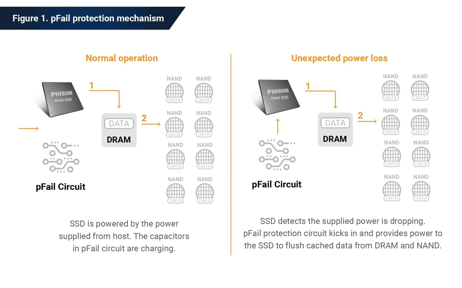
As illustrated in Figure 3, the PLP circuit executes an uninterrupted five-step sequence:
- Step 1 (Steady Charge): Under regular input voltage, the capacitor array trickle-charges to maximum capacity.
- Step 2 (pFail Detection): When input voltage drops below threshold, detection circuitry asserts a
pFailinterrupt in microseconds. - Step 3 (Holdup Power Handover): Main input rails isolate via bidirectional physical blocking; the onboard capacitor array discharges instantly to sustain the controller, DRAM, and NAND rails.
- Step 4 (Emergency Cache Flush): The controller halts host I/O requests and mobilizes all flash channels to flush uncommitted DRAM data and FTL tables to NAND.
- Step 5 (Safe Power Down): Firmware validates metadata checksums, writes integrity flags, and safely closes channel rails to ensure instant recovery on next boot.
4. Power Management IC (PMIC) & Capacitor Circuit Topology
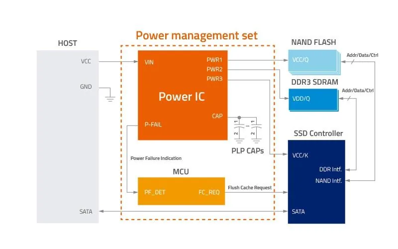
True enterprise-grade PLP relies on dedicated Power Management ICs paired with specialized MCU monitoring logic:
- Instantaneous P-FAIL Interrupt: The Power IC continuously samples input voltage (VIN). Detecting undervoltage immediately fires
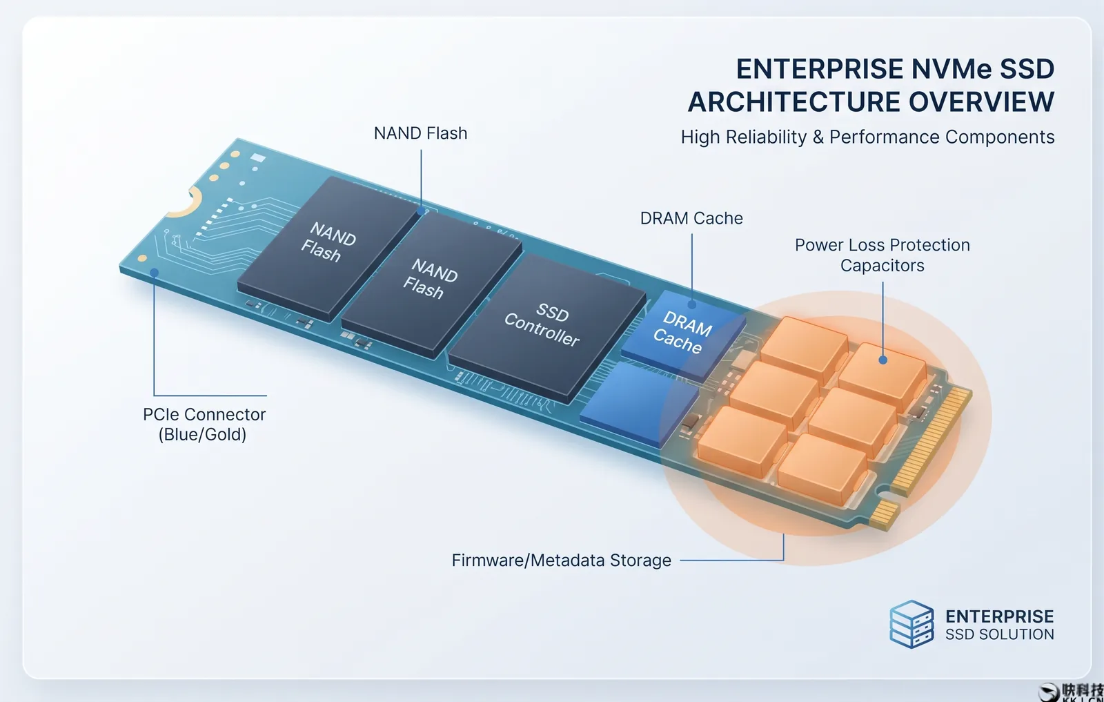
PF_DETto the MCU, dispatching aFlush Cache Requestto the main controller. - Capacitor Discharge Reservoir (PLP CAPs): A high-capacity tantalum capacitor bank buffers surges and provides stable voltage outputs across internal PWR1/PWR2/PWR3 rails during emergencies.
5. Enterprise Hardware Breakdown: High-Density Tantalum Capacitor Arrays
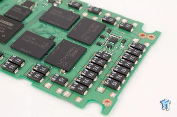
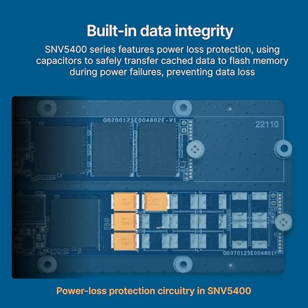
While consumer SSDs eliminate physical capacitors to minimize costs, FuEpoch Vault enterprise SSDs deploy high-grade military/industrial tantalum polymer capacitors along the PCB perimeter:
- Thermal Endurance & Longevity: Tantalum capacitors offer high capacitance density, ultra-low equivalent series resistance (ESR), and zero electrolyte dry-out risk under 85°C sustained server environments.
- Millisecond Holdup Capacity: Onboard energy reserves are calibrated to comfortably outlast worst-case multi-channel flash write latencies (~15ms to 40ms).
6. M.2 22110 Industrial Form Factor & Data Integrity Assurance
Because hardware PLP capacitors require substantial PCB real estate, standard consumer M.2 2280 boards cannot house full protection circuits. Enterprise datacenters predominantly standardize on the elongated M.2 22110 form factor (110mm):
| Protection Tier | Hardware Capacitor Setup | FTL Mapping Table Protection | DRAM Buffer Protection | Reliability Grade |
|---|---|---|---|---|
| Enterprise Hardware PLP (FuEpoch Standard) | Dedicated Tantalum Capacitor Banks | 100% Full Integrity Protection | Completely Flushed to NAND (Zero Loss) | Financial / Mission-Critical Server |
| Pseudo PLP / Firmware Only | No Physical Capacitors | Relies on residual inductor power; high corruption risk | Unflushed DRAM data completely lost | Low |
| Standard Consumer SSD | No Physical Capacitors | Relies on clean OS shutdown commands | Sudden power off causes instant data loss | Consumer / Gaming |